-
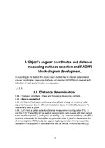
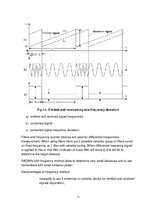
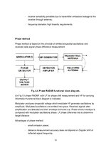
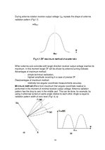
The Development of Airborne Weather Radar System
Реферат55 Компьютеры, программирование, электроника, Физика, Коммуникации, транспорт, связь


| Nr. | Название главы | Стр. |
| 2. | Zondējoša signāla parametru izvēle | 22 |
| 2.1. | RADARA raidītāja viļņa garuma izvēle | 22 |
| 2.2 | Zondējoša signāla sekošanas perioda izvēle | 26 |
| 2.3. | Zondējoša signāla ilguma izvēle | 26 |
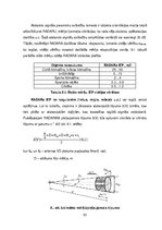
| 3. | RADARa antenas parametru aprēķins | 27 |
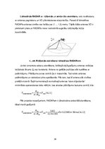
| 3.1. | Antenas versuma diagammas izvēle | 27 |
| 3.2. | Antenas virziena diagammas izvēle Zemes virsmas apskatei | 27 |
| 3.3. | Antenas izmēri | 28 |
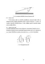
| 3.4. | Antenas formas izvēle | 28 |
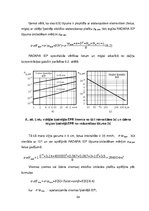
| 3.5. | Antenas VD platums pie pusjaudas līmeņa (-3 DB) un sanlapju līmenis | 29 |
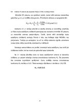
| 3.6. | Antenas efektīvais laukums | 30 |
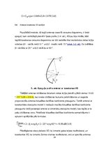
| 3.9. | Antenas kosekansa VD aprēķini | 32 |
| 4. | Gaisa telpas novērošanas parametru aprēķināšana | 33 |
| 4.1. | Novērošanas metodes izvēle | 33 |
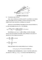
| 4.2. | Pamatattiecības secīgai novērošanai | 34 |
| 4.3. | Skenēšanas tipa izvēle | 35 |
| 5. | Radio-uztverēja parametru aprēķināšana | 37 |
| 5.1. | Izšķirtspējas koeficienta aprēķināšana | 37 |
| 5.1.1. | Impulsa signāla noteikšanas parametrs | 37 |
| 5.1.2. | Zudumu aprēķins pie signāla apstrādes | 39 |
| 5.1.3. | Uzkrāto impulsu skaits impulsu pakā aprēķins | 41 |
| 5.2 | Radiouztvērēja trokšņa jaudas aprēķins | 41 |
| 6. | RADARa izsķirspējas aprēķins | 44 |
| 6.1. | Potenciālas izšķirtpējas aprēķins | 44 |
| 6.2. | Indikatora potenciālās izšķirtspējas novērtējums | 45 |
| 6.3. | Reālās izšķirtspējas aprēķins | 46 |
| 7. | Mērķu koordinātu mērījumu precizitātes aprēķins | 47 |
| 8. | Objekta izkliedes efektīvas platības aprēķins | 49 |
| 9. | Raidītāja jaudas un RADARA darbības tāluma aprēķins | 53 |
| 10. | Secinājumi | 54 |
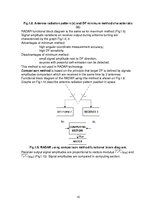
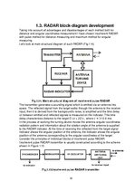
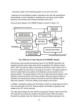
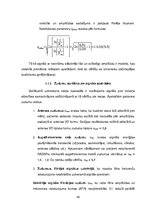
Fig.1.18.Structural block diagram of the RADAR indicator.
Synchronizer pulse provides simultaneous launch of the RADAR transmitter and sawtooth generator pulse range sweep which are applied to the deflection system (EBF). When the antenna rotation is switched off the electron beam draws a line on the screen radially from the center to the edge of the screen. The angular position of this line is determined by the position of the deflection coil and conforms to the antenna position. The angular position of this line is determined by the position of the deflection coil and conforms to the antenna position. When the antenna rotation is switched on the synchronous rotation of the antenna and CRT deflection system begin their operation. This forms radially circular sweep on the screen.
In addition, rectangular pulses for the illumination of direct run range sweep are fed to the control electrode of the CRT. Reverse sweep is terminated by applying a bias voltage to the CRT control electrode.
The video signal voltage from the receiver’s output goes through a video mixer to the CRT cathode and controls the intensity of the electron beam. When the ignition threshold is exceeded under the influence of this ray luminophore glowing on the screen begins. The brightness depends on the intensity of the electron beam. As a result, the screen displays the brightness marks from the targets, local terrain features and rain formations, etc.
…
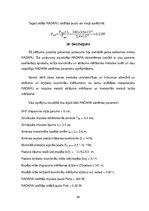
Šā pētījuma projekta galvenais uzdevums bija izstrādāt gaisa satiksmes meteo RADARU. Šis uzdevums paredzēja RADARA blokshēmas izstrādi ar visu galveno sastāvdaļu aprakstu, leņķa koordinātu un attāluma mērīšanas metodes izvēli un visu vajadzīgo RADARA sistēmas parametru aprēķināšanu.
Angļu un latviešu valodā.